Have you ever considered building a motion capture system for a boutique robotics project, only to be deterred by the high cost of commercial solutions? In this post, we show how to build a low-cost motion capture system using Bitcraze’s Lighthouse Positioning deck for the Crazyflie drone, some solder and ROS.
The Lighthouse Positioning System
Motion capture systems are essential for many robotics applications: they track the position and orientation of robots in real time, provide ground truth data, or can be used to replace a robot’s internal state estimation entirely.
Unfortunately, commercial motion capture systems are often prohibitively expensive — especially for hobbyists and small research projects. They are designed for high-end, professional use cases, and their price tags reflect that.
Lighthouse is the name of a proprietary localization system that was developed by Valve for use with the HTC Vive virtual reality system. A combination of infrared emitting stations and sensors is used to track the position and orientation of objects in a 3D space. The system is known for its great accuracy and low latency. It will also not break the bank, so a community of makers and researchers has been inspired to repurpose it for robotics applications.
The Lighthouse system itself is relatively simple. It is composed of two main components: the base stations and the sensors. The stations are typically mounted high on a room’s walls or ceiling.
There are two versions of the system; the first version (V1) uses two stations with orthogonal rotation axes, while the second version (V2) uses a single station with a single rotation axis. Both versions are still widely used and supported by the Lighthouse deck, and the principles of operation are similar in both cases.
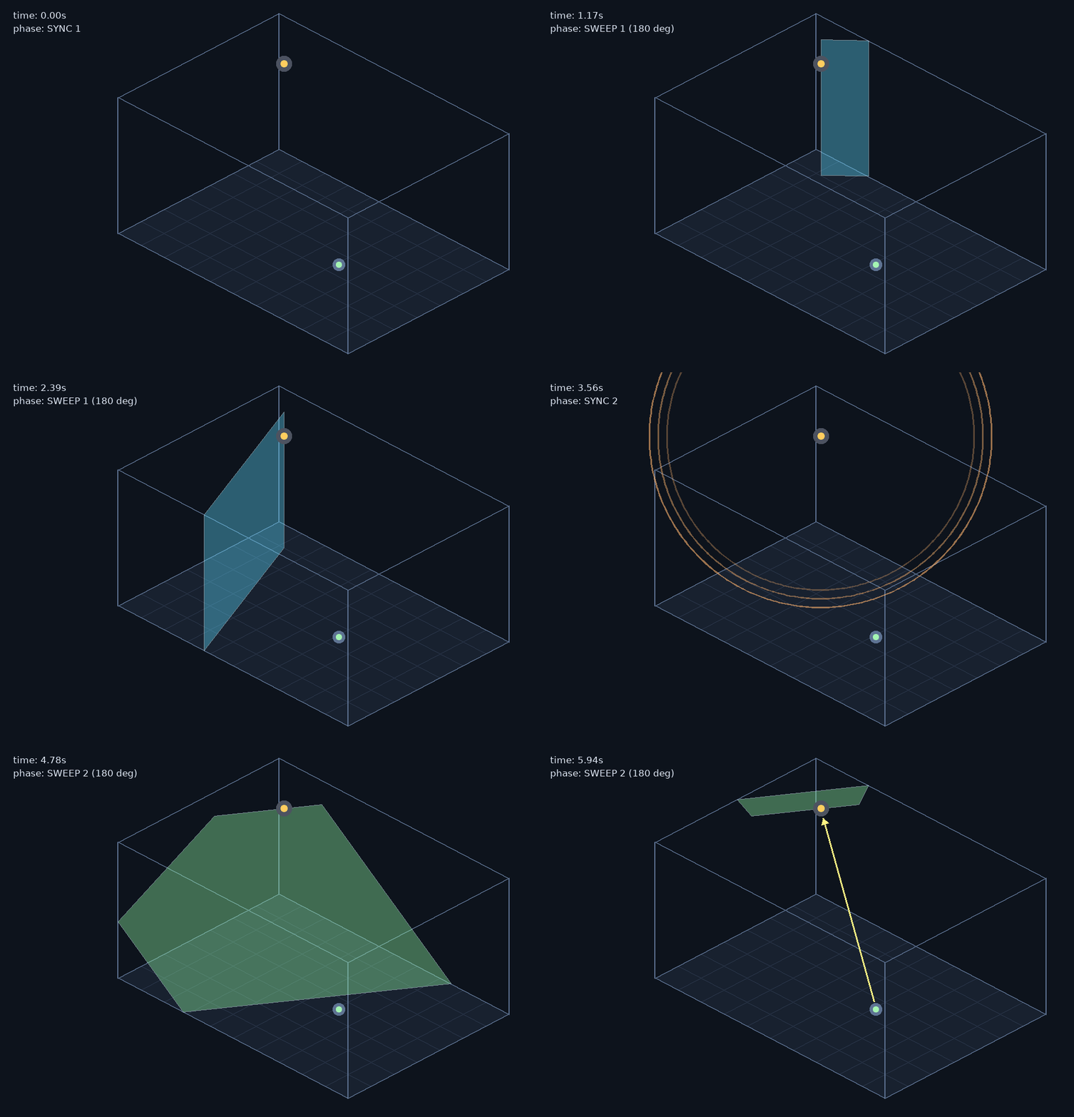
V1 stations are the easiest to understand. They have two orthogonal rotating cylinders that periodically sweep a plane of infrared light across the room, first one cylinder, then the other. Before each sweep starts, an omnidirectional flash of infrared light is emitted as a synchronization pulse. Receivers detect the sync pulse and then measure the time difference between the sync and the sweeping plane of light hitting their sensors. Since the angular velocity of the sweep is known, this time difference can be converted into an angle relative to the station. Using the angle from both the horizontal and vertical sweeps, the receiver can determine its bearing in 3D space relative to the station.
V2 stations are based on the same principle of sweeping planes of light, but their design is more complex. These stations use a single rotating cylinder that sweeps the room with two consecutive planes of light, one after the other. These planes are not parallel, but instead are angled with respect to each other so that they form a V shape; this relative inclination between them makes it possible to encode elevation information in the time difference with which both planes hit the sensors.
The azimuth information is encoded in the timing of the sweeps themselves, but instead of using a synchronization pulse to mark the start of each sweep, V2 stations encode a digital signal directly on the light sweeps that the receiver can decode to determine the relative phase of the sweep at the time it hits the sensors.
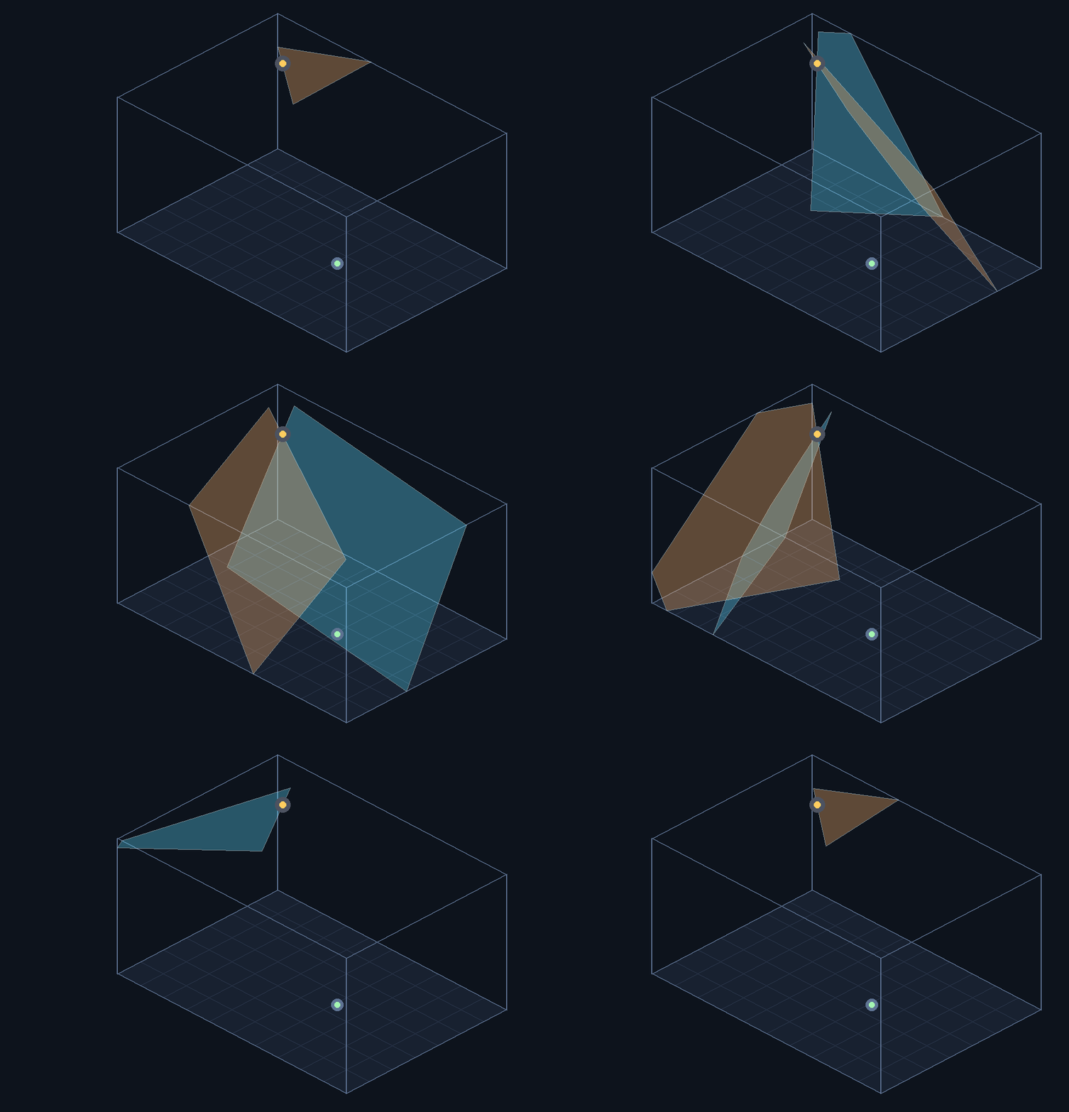
This extra complexity in the design of V2 stations has a number of advantages. First and foremost, their mechanical design is simpler, which makes them cheaper to manufacture and more robust. Also, the lack of the synchronization pulse allows multiple V2 stations to operate in the same space without any interference between them, while V1 stations needed to take turns to avoid receivers being confused by the sync pulses of different stations. More information about the differences between versions can be found in Bitcraze’s Lighthouse V2 article.
So far we discussed how a single sensor can determine the bearing to a single station, but this is not enough to determine the sensor’s full 3D position. The distance to the station remains undetermined, so additional information is needed to resolve the full 3D position.
We can get this information in at least two different ways:
- By using multiple stations with known relative poses. Each station provides a bearing, and triangulating those bearings yields the receiver’s position.
- By using multiple receiver sensors with known relative positions. With four sensors it is possible to determine not only the position but also the orientation of the receiver relative to the station.
The Lighthouse positioning deck
Bitcraze is the company behind the well known Crazyflie nano drone. Multiple localization solutions for the Crazyflie drone are commercialized by Bitcraze, including the Lighthouse positioning deck. This is a small hardware add-on for the Crazyflie drone that allows the Lighthouse positioning system to be used as a localization source using standard HTC Vive or SteamVR stations.
This hardware is not only affordably priced but also open source, which means that it can be modified and customized to fit specific needs.
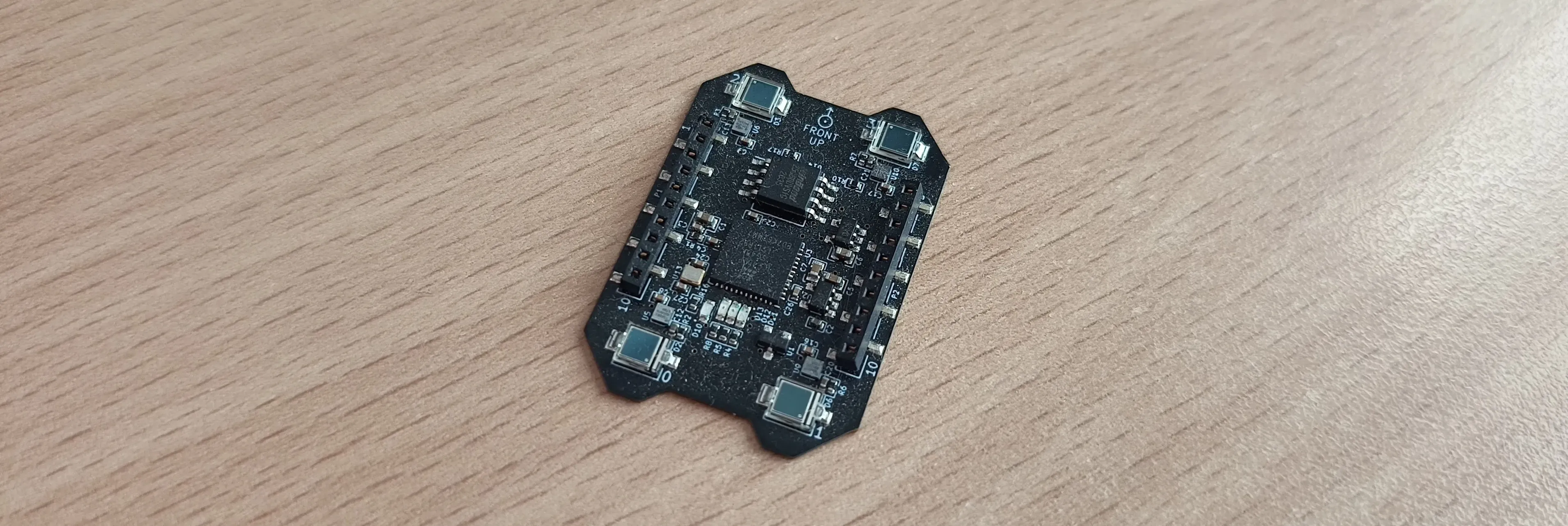
The hardware itself is built around a small FPGA device that processes the signals from four infrared sensors located in the corners of the board. This FPGA synchronizes with stations and measures the time differences between the sync pulses and the light sweeps. It then sends the data through a serial link to the Crazyflie drone’s main processor. Once there, the raw data is decoded, converted into bearing measurements, and finally used to estimate the receiver’s position.
Since there are four sensors, the deck can be used to estimate the receiver’s full 3D pose even if only a single station is present. Multiple stations can be used to extend system coverage and improve accuracy, but they require a calibration process to determine their relative poses.
This Lighthouse deck is specifically tailored for the Crazyflie drone, and depends on the drone’s main processor and host software for most of its functionality. For this reason, since we want to be able to use it in ROS, some work will be necessary before we can use it as a standalone motion capture system:
- Interfacing with the hardware
- Decoding the raw sensor data
- Calculating the receiver’s pose
Interfacing with the Lighthouse deck hardware
The deck uses a serial link to communicate with the Crazyflie drone’s main processor, so we can easily interface it with a computer using a USB-to-serial adapter. Any USB-to-serial adapter will do, but it is important to keep in mind the electrical compatibility between the deck and the adapter.
The USB-to-serial adapters typically carry 5V or 3.3V digital signal levels, but the FPGA in the deck operates at 3.0V logic levels. This means that without proper voltage level shifting, the FPGA could be damaged by higher voltage levels of the adapter. This level shifting is only necessary for the RX pin of the FPGA, since the TX pin of the FPGA will be outputting signals at 3.0V levels, which are safe for the adapter to receive.
This means that while the TX pin on the FPGA can be directly connected to the RX pin of the adapter, the RX pin on the FPGA must be protected by mediating the connection with a voltage divider to ensure that the voltage levels are compatible and to prevent damage to the FPGA.
A simple voltage divider can be made with two resistors. If your USB adapter works with 5V levels, a simple voltage divider can be made with two 10kΩ resistors. If your adapter works with 3.3V levels, a voltage divider can be made with a 10kΩ resistor and a 20kΩ resistor.
Note: These instructions are for a generic USB-to-serial adapter. Always check the datasheet of your specific adapter and the Lighthouse deck, as the pinout, labelling, and signal levels may vary.
The adapter 5V output needs to be connected to the VBAT pin of the deck to supply power to the FPGA and sensors, and the ground pins of the deck and the adapter need to be connected together. The TX pin of the deck needs to be connected to the RXO pin of the adapter. The RX pin of the deck needs to be connected to the voltage divider (R1 and R2), which in turn needs to be connected to the TXO pin of the adapter. Additionally, a pull-down resistor (R3) connects the RXO line to ground to ensure proper signal levels (equivalent to a break signal) when the TX line from the FPGA is tri-stated.
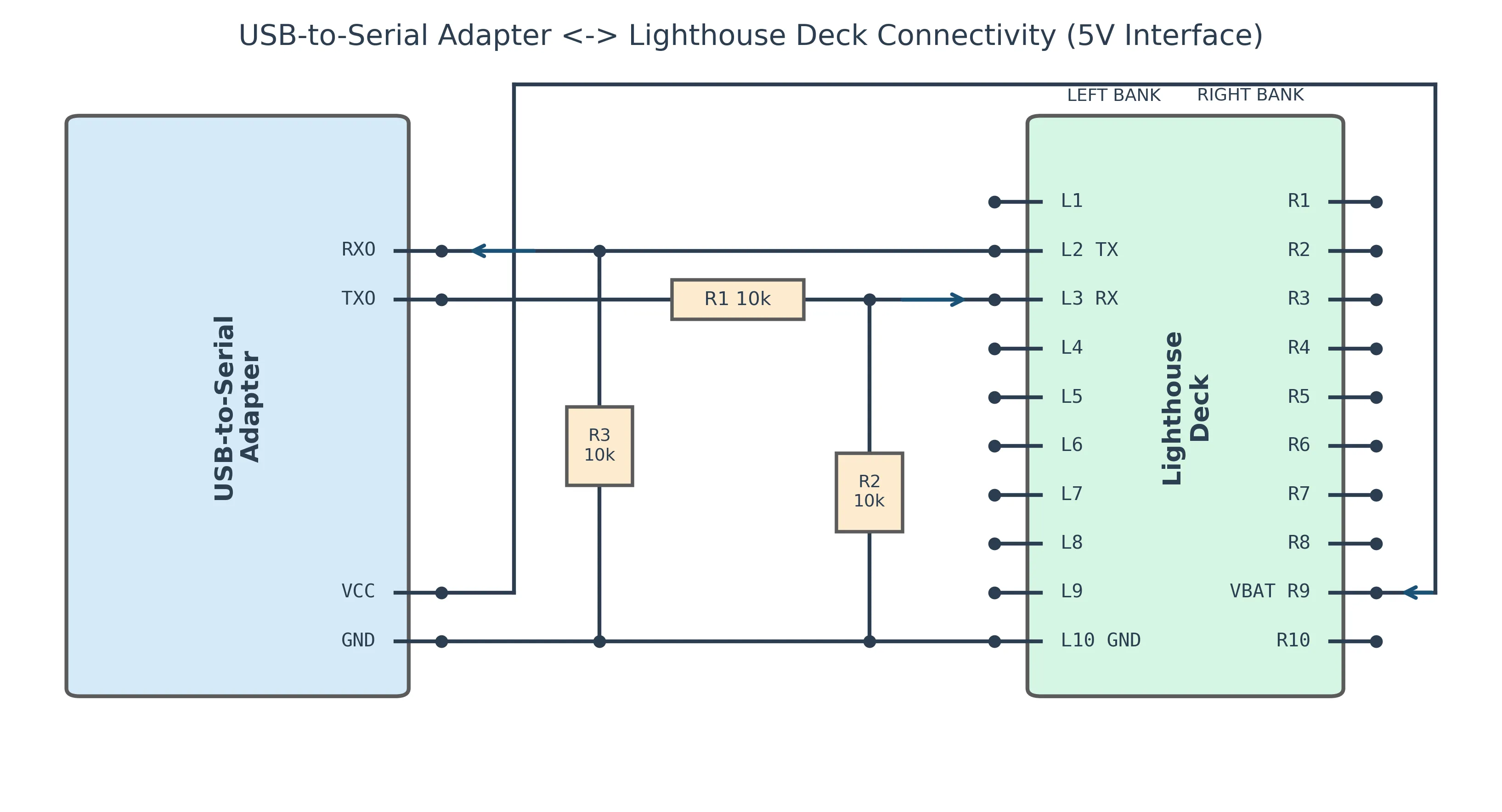
If in doubt, check the deck’s schematics.
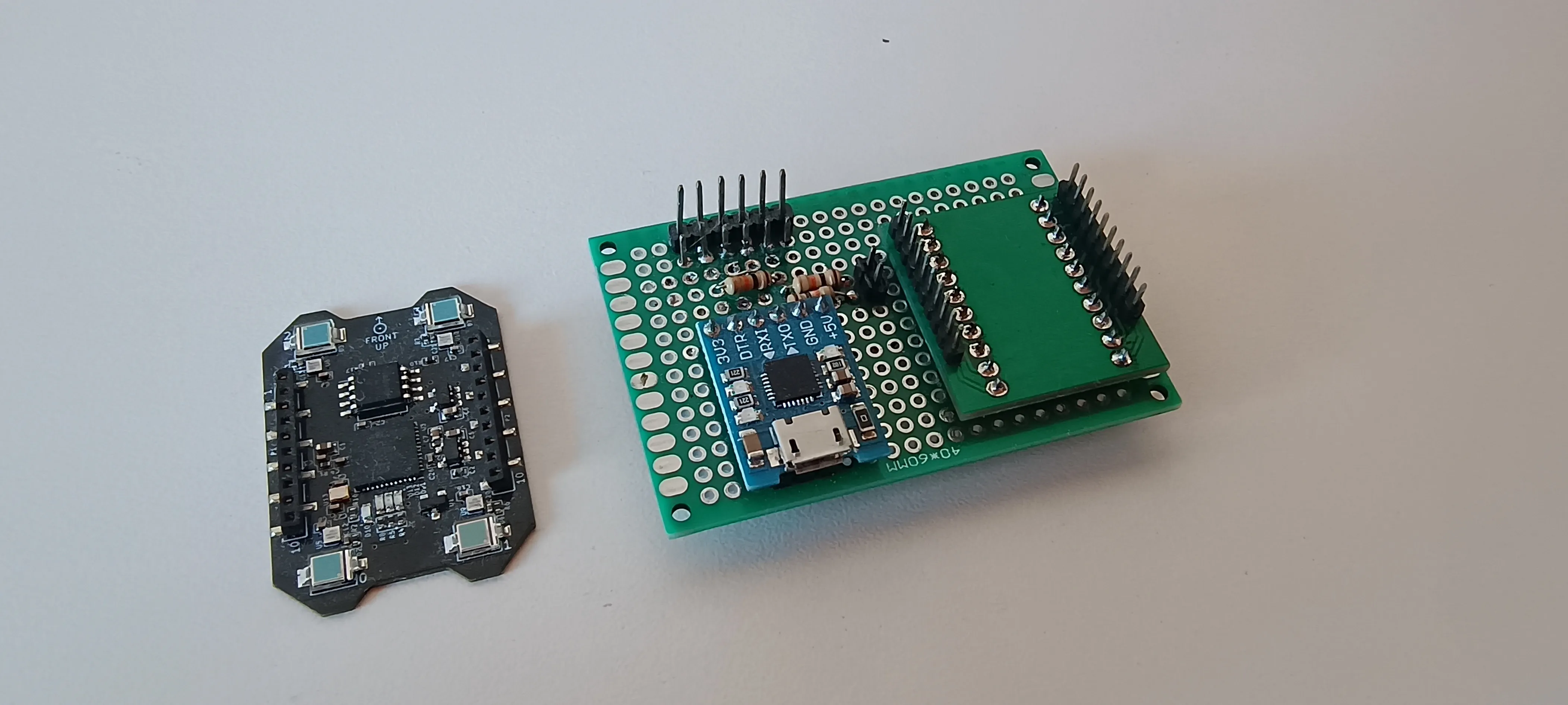
The easiest way to build this adapter is to use a breadboard, which allows for easy modifications and adjustments. The deck has two rows of pins with 2mm spacing, which is not compatible with the standard 2.54mm spacing of breadboard components. Fortunately, the deck’s pins are a perfect match for XBee breakout boards, such as this one from SparkFun, which can be used as an intermediate adapter to connect the deck to the breadboard. If you use an XBee breakout board, make sure to ignore the pin labels on the board, as they are not relevant for the Lighthouse deck and could lead to confusion.
The result will be a setup like the one shown below.
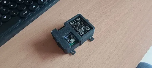
The board should be protected with a case to safeguard the electronics and make it easier to attach to the tracked object.
Booting the deck into data transmission mode
Once we have the hardware set up and connected to the computer, we can start decoding the raw sensor data. The deck sends data through the serial link in a specific format, and we need to understand this format to extract the relevant information for pose estimation.
When the deck is first powered on, it will not be sending data through the serial link. Instead, it will be running a small bootloader that waits for commands on the UART arriving at 115200 bauds, with 8 data bits, no parity, and 1 stop bit (115200 8N1). Also, the TX line of the deck is initially disabled: the bootloader will listen, but the TX pin will be tri-stated for safety, until a specific command is received from the host to enable it.
To enable the TX line and start the main firmware that processes the sensor data, the host needs to send a specific sequence of commands to the bootloader. First, a command to enable the TX line (0xBC) must be sent, followed by a second command to start the main firmware (0x00).
This sequence will cause the bootloader to start the execution of the main firmware in the FPGA, which will then begin processing the sensor data and transmitting it through the serial link. The main firmware will reconfigure the UART to 230400 8N1 at this point, so the host needs to adjust its settings accordingly to continue receiving data.
Decoding the sensor data
For the sake of brevity only the main points of the protocol used to transmit the sensor data are covered here. For a complete description, see Bitcraze’s FPGA documentation.
At the lowest level, the data is transmitted in 12-byte packets. Twice each second, an “all-ones” packet is sent for synchronization purposes. The rest of the time, the data packets contain several fields:
Loading graph...
---
config:
  packet:
    bitsPerRow: 24
---
packet-beta
  0-1: "SID"
  2-7: "nPoly"
  8-23: "Width"
  24-40: "Sync Offset"
  41-47: "Reserved"
  48-64: "Beam Word"
  65-71: "Reserved"
  72-95: "Timestamp"
The receiver needs to group into sets of four dataframes that make a sweep. A sweep contains the timing information for the arrival of a single light sweep to all four sensors of the deck.
These sweeps are next paired in twos to identify the two planes of light emitted by the station in a single measurement cycle. For V1 stations, these will be the horizontal and vertical sweeps, while for V2 stations, these will be the first and second planes of the V-shaped sweep.
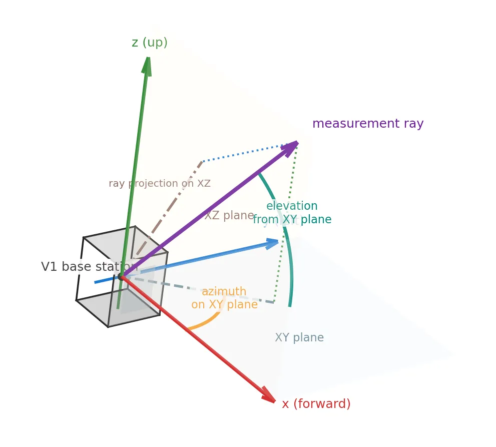
Finally, the azimuth and elevation relative to the station frame are derived from the timing information in both sweeps. These are measured relative to the front of the station, with the azimuth increasing leftwards and the elevation increasing upwards.
Decoding station calibration data
There is also a second layer to the protocol: each data packet embeds a single bit — the “slow bit” — in the nPoly field. The sequence of these bits forms a slower secondary stream with its own protocol called OOTX, carrying variable-length frames that contain calibration data for the transmitting station.
We will not cover the details of the OOTX protocol here, but it is worth noting that decoding this information would allow us to use the station’s calibration data, which can improve the accuracy of the system. This is left for future work.
Estimating the receiver’s pose
At this point it is possible to obtain the azimuth and elevation angles of the receiver relative to one or more stations. This information can be used to estimate the receiver’s pose in a number of ways.
Perspective-n-Point (PnP) Method
The simplest method, though also the most limited, is to estimate the pose of the receiver relative to a single station from a single set of measurements. This can be done elegantly by mapping the Lighthouse pose estimation problem onto the Perspective-n-Point (PnP) problem from computer vision.
PnP is a well-known problem in which the pose of a camera is estimated from the projection of a set of known 3D points onto its image plane. By treating the station as a camera and projecting the sensor angular measurements as points onto a virtual image plane, the receiver’s pose can be estimated using widely available PnP solvers such as those in OpenCV.
This method is simple and computationally efficient, but is limited to determining the pose of the deck relative to a single station. If multiple stations are present, their relative poses must be established by other means, and the receiver’s pose can only be estimated with respect to one of them, leaving the redundancy of the system unexploited.
Bundle adjustment
A more sophisticated approach is to estimate the pose of the receiver relative to all the stations simultaneously by formulating the problem as a non-linear optimization problem. This method can exploit the redundancy and potentially improve the accuracy of the pose. For this to work, however, the measurements to all stations must be captured simultaneously, or at least the receiver must be static while the measurements are captured, so that they can be considered as simultaneous.
Determining the station relative poses
When there’s a single station in the workspace, either of the methods described above can be used to estimate the pose of the receiver relative to that station, taking that station as the origin of the world frame. It’s also relatively straightforward to later offset this origin to a more convenient location if needed, by simply applying a fixed transformation to all the poses estimated from that point on.
When multiple stations are present, however, it’s important we know their relative poses in order to be able to get consistent pose estimates from all of them relative to a common frame.
Fortunately the station relative poses can be solved as a bundle adjustment problem too: by sampling the bearing angles to multiple stations from multiples deck poses in the workspace, we can then build an optimization problem that will simultaneously estimate the poses of the stations (the relative poses we are interested in) and the deck poses at which the measurements were taken, by minimizing the overall error across all measurements.
This process usually only needs to be performed once, unless the stations are moved.
Software implementation
We have open-sourced the software side of the interface in our GitHub repository. It contains several ROS packages that implement the necessary functionality to interface with the deck, decode the sensor data, and estimate the station relative poses.
The protocol decoding and deck interaction algorithms are based on the Crazyflie drone’s firmware, FPGA, and bootloader. Currently, only the first layer of the protocol is implemented, with OOTX decoding left for future work.
A simple ROS-based text-based interface application is provided to help with the workflow of calculating the station relative poses. This application will allow the user to sample the measurements from multiple deck poses with simultaneous visibility of two or more stations, run the solver to calculate the station relative poses, and export the resulting relative poses to a file for later use. The solver itself is based on Ceres, a popular non-linear optimization library widely used in the robotics and computer vision communities.
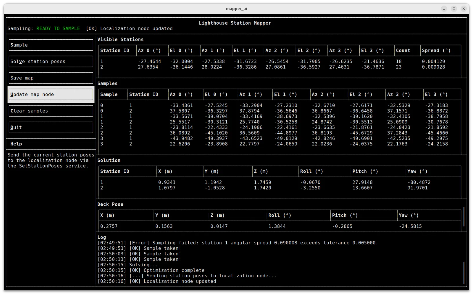
A different ROS node is provided to do pose tracking, by calculating the pose of the deck when the station relative poses are already known. This node can be used to track the pose of the deck in real time, and publish it as a ROS topic for use by other nodes in the system. At the time of writing, the tracking node does not perform any filtering on the solutions, but this is an area for future improvement.
Well, does it work?
We tested the system using two Lighthouse V2 stations and a single deck. As mentioned earlier, we only decode the first layer of the protocol and do not use OOTX station calibration data, which would likely improve system accuracy. Additionally, we do not perform any filtering on the pose estimates.
While we lack independent ground truth measurements, we evaluated the system’s accuracy by measuring the error in determining relative poses between known workspace locations. Our experiments suggest this implementation achieves accuracy within a few centimeters. For a more in-depth analysis with systematic measurements, the team at Bitcraze has published comprehensive accuracy evaluations.
For a qualitative demonstration, we mounted the deck on a small omnidirectional mobile robot and tracked its pose as it moved around the workspace. The two V2 stations were mounted 2.1 meters above the ground, spaced two meters apart, and angled slightly downward.
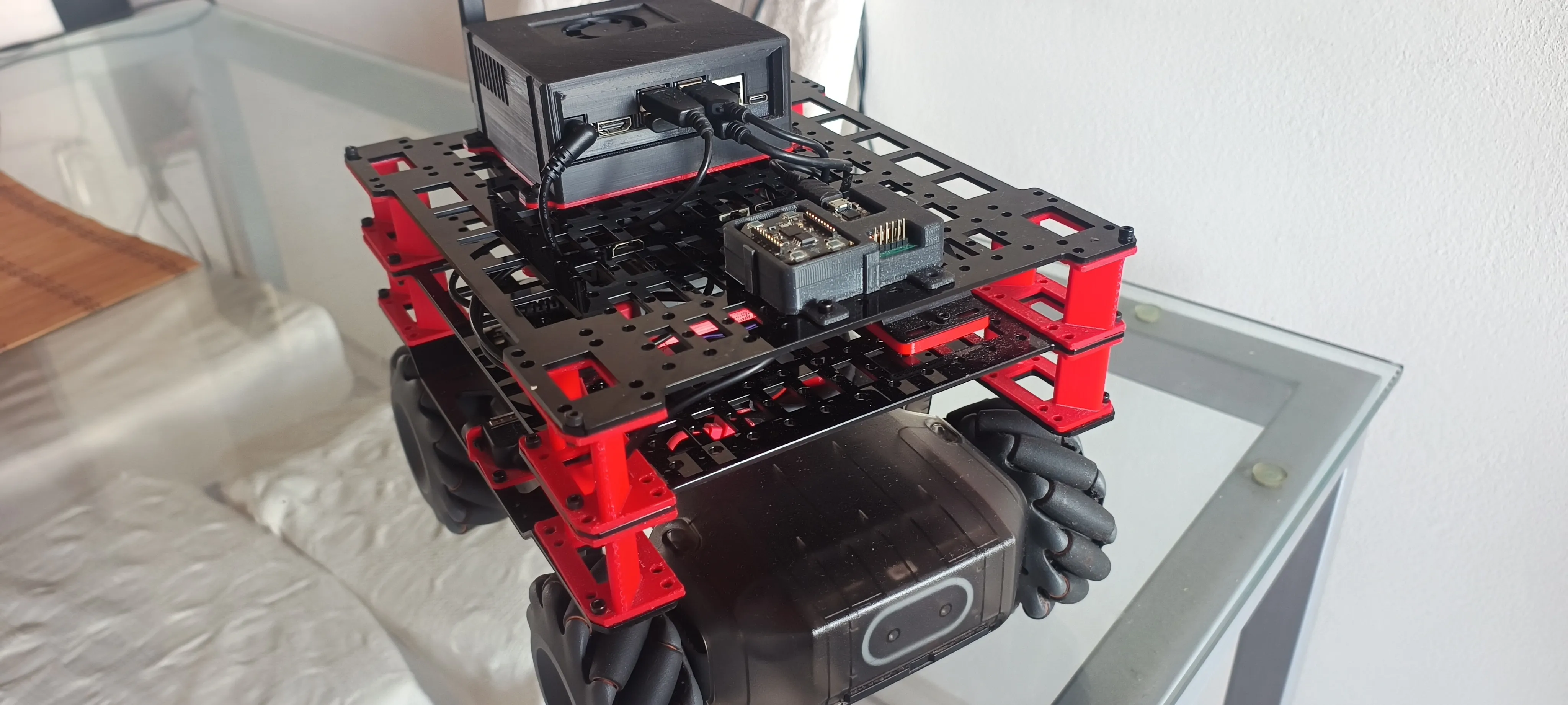
The recording below demonstrates the complete workflow: we start by collecting measurements as the robot moves around the workspace, then run the solver to calculate the station relative poses, and finally send the geometry data to the tracking node, which begins publishing real-time pose estimates.
Conclusion
The Lighthouse Positioning system is a fun and affordable motion capture solution that can be repurposed for multiple applications. By interfacing with the Lighthouse deck hardware, decoding the raw sensor data, and estimating the receiver’s pose using techniques like PnP and bundle adjustment, it is possible to build a custom motion capture system that delivers good accuracy and performance, and it’s a fantastic option for hobbyists, researchers, and anyone looking to experiment with motion capture without breaking the bank.
We wanted to bring this wonderful system closer to the ROS community, but our implementation is just a conversation starter. There are many areas for improvement and optimization, and we encourage anyone interested to check out the code, report issues, or even better, contribute to the project! We look forward to seeing how the community can expand on this work and make it even better.
Feel free to visit the GitHub repository to check out the code, report issues, or even better, contribute to the project!
Acknowledgements
The people at Bitcraze developed and commercialized the Lighthouse deck, which is the core hardware component that made this project possible. They have also generously shared extensive information online about the hardware of the deck, the accuracy of the system, the models needed to obtain angular measurements, and many posts such as this one about improved station geometry estimation. On top of that, they made available the source code for the implementation of the Lighthouse code in the Crazyflie firmware, the deck FPGA, and the bootloader.
Said Alvarado-Marin presented a talk on repurposing SteamVR technology for robotics and the accompanying slides at last year’s FOSDEM conference, which serves as an excellent resource on the low-level details of the Lighthouse system.
Lots of other people have also contributed to the understanding of the Lighthouse system over the years, and their work can be found scattered across the internet, the list would be too long to include here.
A big thank you to all of them for their work, which made this project possible and hopefully will make it easier for others to build on top of it!